A rack of AI accelerators now puts out more heat than air cooling can carry away. Once cooling goes liquid, the engineering question shifts from how to move air to how to move fluid. The cold plate itself is the settled part of the path — it sits on the chip and does its job. The hard part is getting coolant into it and back out again, reliably, through a chain of joints, not one of which can leak.
Good Gi supplies hoses, quick disconnects, and thermal management materials along that path. This article walks the coolant from the coolant distribution unit (CDU) to the chip and explains what each segment connects with, and why the two methods can't be swapped.
Where the cold plate sits in the system
A cold plate is a metal plate with internal flow channels, clamped directly onto a CPU, GPU, or power device. Coolant runs through the channels and carries the heat out. This is direct-to-chip (D2C) liquid cooling, a different approach from immersion cooling, where the whole board goes into the fluid.
Working outward from the heat source, heat from one chip crosses three interfaces before it leaves the rack:
| Interface | What moves the heat | What matters here |
|---|---|---|
| Chip ↔ cold plate base | Thermal interface materials (gap pads, gap fillers, phase change materials) | Even two machined surfaces leave microscopic voids, and trapped air insulates. A compliant material has to fill them |
| Cold plate ↔ coolant | Internal flow channels | The channels are narrow and clog easily, so the coolant has to stay clean |
| Coolant ↔ outside the rack | Hoses, fittings, manifolds, CDU | The subject of this article |
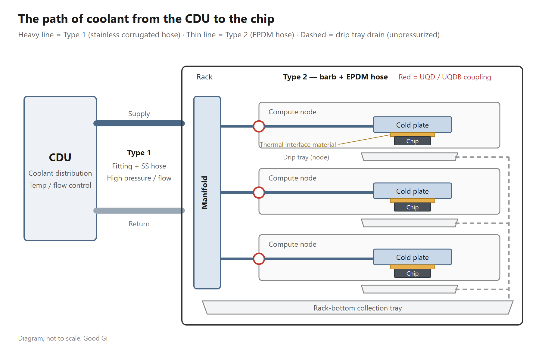
The full path of one loop of coolant. Heavy lines are the primary level, thin lines are inside the server, and the two use different tubing. Schematic, not to scale
A drip tray usually sits below the cold plate to catch anything that escapes, with a small hose to carry it clear of the equipment. That hose is sized by exactly the opposite logic from a coolant line, and it has its own article: how to choose a drip tray drain hose.
What determines how a run of tubing is built is which level it sits on. Both segments carry the same coolant, but the primary lines outside the rack and the plumbing inside a server drawer are built from two different sets of materials.
Primary level and node level: what changes
These two terms come up throughout, so here is the difference up front:
| Primary level | Node level | |
|---|---|---|
| Location | Outside the rack: CDU ↔ rack manifold, plus runs under the floor and between racks | Inside the rack: manifold ↔ compute node, cold plate ports ↔ internal node plumbing |
| Who it feeds | The whole rack, dozens of chips sharing one loop | A single node, sometimes a single cold plate |
| Pressure and flow | Everything the pump moves goes through here — the highest pressure and velocity in the system | One branch after the split; both pressure and flow drop |
| Line size | Large | Small |
| Who touches it | Facilities mechanical crews, on a maintenance schedule | Server operations staff, whenever a module is swapped |
| Service frequency | Low, installed and left alone | High |
| What a leak costs | The whole rack, possibly a whole row | One node — but directly above live boards |
| Material priority | Pressure rating, corrosion resistance, service life, mechanical protection | Flexibility, vibration damping, small bend radius, fast disconnect |
The primary level is judged on how much pressure it holds and how long it lasts. The node level is judged on whether it bends into the space and comes apart quickly. That is where the material choice splits.
Type 1: fittings and stainless corrugated hose (primary level)
| Where it goes | What it connects |
|---|---|
| Rack manifold ↔ CDU | Supply and return lines for an entire rack |
| Under the raised floor, between racks | Fixed or semi-fixed large-bore distribution piping |
Choosing between serviceable and permanent joints
| Type | Characteristics | Where it fits |
|---|---|---|
| Serviceable (threaded, flanged, quick disconnect) | A single section can be replaced on its own | Positions that need scheduled maintenance or may be reconfigured later |
| Permanent (welded) | Highest joint strength and the tightest seal, with no gasket to age | Fixed runs buried in the structure, rarely if ever disturbed |
In practice the two get mixed: serviceable fittings at the equipment end where maintenance happens, welded joints along the long middle run.
End connection types
Serviceable versus welded decides how you maintain the line. What you have to agree on with a supplier is the end connection. Stainless corrugated hose ends fall into roughly seven families:
| Family | Codes | Where it is used |
|---|---|---|
| Pipe end | PA, PB | The plainest straight end, butt-welded or socket-welded in the field |
| Pipe end, metal seal | RF, RM | Metal-to-metal sealing with no elastomer, suited to high-purity and high-temperature service |
| Pipe end, O-ring seal | OF, OM | O-ring sealing, fast to service; the seal compound has to match the coolant chemistry |
| Vacuum flange | KF, IK (ISO-K), IF (ISO-F), CF | Standard interfaces for vacuum and semiconductor process lines |
| Spherical metal seal | SF, SMN / SMR, SFN / SFR | Spherical seating, available with NPT or R threads to land on existing piping |
| Fluid flange | FF | Flanges for liquid transfer, common on liquid cooling primary lines |
| Union | WF, WM | Union joints, so the hose body doesn't have to rotate during service |
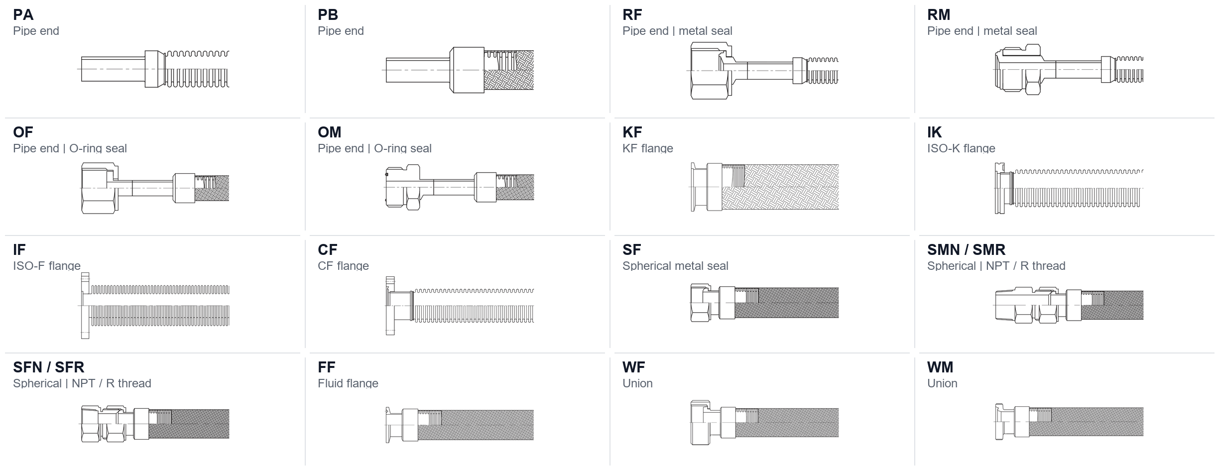
Sixteen end connection types and their codes. The two ends of one hose can differ, each matched to the equipment it lands on
The flange family — KF, ISO-K, ISO-F, CF — comes from vacuum and process piping and is uncommon in liquid cooling. Primary cooling lines usually land on fluid flange FF, spherical metal seals, or plain pipe ends.
End sizes follow the dash-size convention, where the number is the nominal bore in sixteenths of an inch: 4 = 1/4", 6 = 3/8", 8 = 1/2", 16 = 1", 20 = 1-1/4", 24 = 1-1/2", 32 = 2". Quotes are normally written as one combined code — series code (braided or unbraided) – end 1 code – end 2 code – overall length – material code — for example FB-PA4-PA4-300-M1, where 300 is the overall length in millimeters. Codes vary by manufacturer, so sending an interface drawing with your RFQ is more reliable than quoting a code.
Why this segment runs stainless
The pressure and flow are in a different class. The primary line moves coolant for a whole rack, at pressures and velocities well above anything inside a single server. Metal corrugated hose has the tensile strength and pressure rating to take it without the wall swelling. Rubber hose at the same duty needs either a thicker wall and more reinforcement or a larger bore, and neither is a good trade in cost or space.
Coolant purity has to hold up over years. Liquid cooling loops commonly run deionized water or a glycol-water mix. Anything the pipe wall releases travels around the loop and ends up in the narrow channels of a cold plate. Electropolished 316L stainless leaves a smooth surface that doesn't shed contaminants, and the loop neither rusts nor scales. It is also why metal fluid components are ultrasonically cleaned and clean-packed before shipment — weld spatter left in a line becomes debris the moment the system runs.
The joints hold their seal. Flame rating is not the dividing line here; braided EPDM hose is available in compounds compliant with UL 94 V-0, and both materials meet a data center's fire requirements. The difference is at the joint. A clamp seals by clamping force, and rubber takes a compression set over time, so that force decays. A welded joint has neither problem and no gasket to age. Metal hose also doesn't embrittle, and it survives the knocks and abrasion of installation and maintenance. For positions nobody plans to shut down once the room is built, the usual choice is the one that never goes on a replacement schedule.
What to check before you buy
Stainless corrugated hose is not a length of tube with a fitting screwed on. Quality varies mostly in the welding and the inspection. Worth writing into your purchase spec:
- Material grade: 316L, 304L, or 2205 duplex; manifolds and headers are also offered in 310S and alloy 602 CA. The grade has to match the coolant chemistry and water quality — a higher grade is not automatically better
- Welding method: laser, TIG, or brazing, depending on the end connection. Ask whether tube-to-tube joints are made on an automatic welder, because that is what keeps weld quality consistent across a batch
- End connection: the seven families above. Confirm the mating interface on the equipment first — get this wrong and the whole batch is scrap
- Pressure rating and elongation: working pressure and burst pressure should be stated separately. Also ask specifically for elongation under pressure — a corrugated hose gets its flexibility from the annular convolutions, and pressure pushes those convolutions open, so the hose grows lengthwise. If both ends are rigidly anchored and that growth has nowhere to go, the hose bows sideways; the industry name for that failure is squirm. Most quotations don't carry this figure, but it decides how much slack you have to leave and whether you can anchor both ends. Restraining the elongation means specifying a braided version, at the cost of flexibility and a larger bend radius. When you ask for the data, confirm whether the sample was unbraided or braided — the two behave very differently
- Test reports: helium leak testing, proof and burst pressure, flow resistance, pneumatic leak testing, thermal cycling, vibration and flex fatigue, and metallographic examination. Agree up front which of these you need, and ask for them with the quotation
- Cleaning and packaging: whether the hose is ultrasonically cleaned and clean-packed before shipment. Weld spatter left inside becomes debris in the loop, and what it blocks is the cold plate
None of this usually appears on a quotation unless you ask.
Type 2: hose barbs and EPDM hose (node level)
| Where it goes | What it connects | Typical joint |
|---|---|---|
| Cold plate inlet and outlet ↔ branch lines inside the node | The single feed this cold plate needs | Hose barb with a clamp or a tie |
| GPU or CPU cold plate module in a drawer ↔ chassis backplane | The interface between module and rack | Blind-mate quick disconnect (UQDB), made by pushing the drawer in |
A hose barb seals by pushing the hose over a tapered, ridged stem and clamping it from the outside. The design is simple and takes up very little room. Everything at this level ties back to the coolant distribution manifold (CDM) at the rear of the rack, which splits what the CDU delivers among the individual nodes.
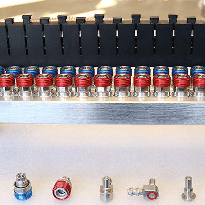
A rack manifold and its couplings. The front row shows several end connection styles
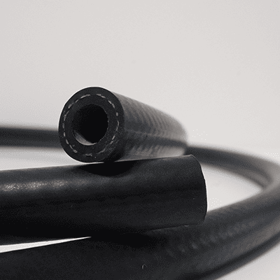
GRAH braided EPDM hose. The textile layer inside the wall carries the pressure, which is what lets a flexible hose hold working pressure
Why this segment runs rubber
The space is tight. Component density on an AI server board is severe, and a line has to thread past memory, cable bundles, and brackets in a gap of a few centimeters. Braided EPDM hose bends through that; a metal hose won't make those turns at this scale, and it leaves no room to adjust during assembly.
There is vibration. Fans and pumps produce continuous low-amplitude vibration. Rubber absorbs it instead of passing it straight into the cold plate and the package underneath. A metal line is stiff, so the vibration travels along the wall and lands on the least robust part in the chain.
Service means disconnecting. Modules at this level get swapped regularly. Joints here are usually liquid cooling quick disconnects (UQD) or blind-mate couplings (UQDB), so pushing the drawer home makes the connection — no depressurizing and no unbolting.
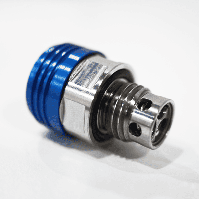
UQD liquid cooling quick disconnect. Spill-free on both halves, so it connects and disconnects while the loop stays pressurized
Selecting braided hose comes down to pressure rating and coolant compatibility: EPDM handles glycol, the braid carries the working pressure, and a compound compliant with UL 94 V-0 covers the fire requirement inside the rack. A typical EPDM service range of −40 °C to 120 °C (−40 °F to 248 °F) spans normal liquid cooling conditions.
The two methods side by side
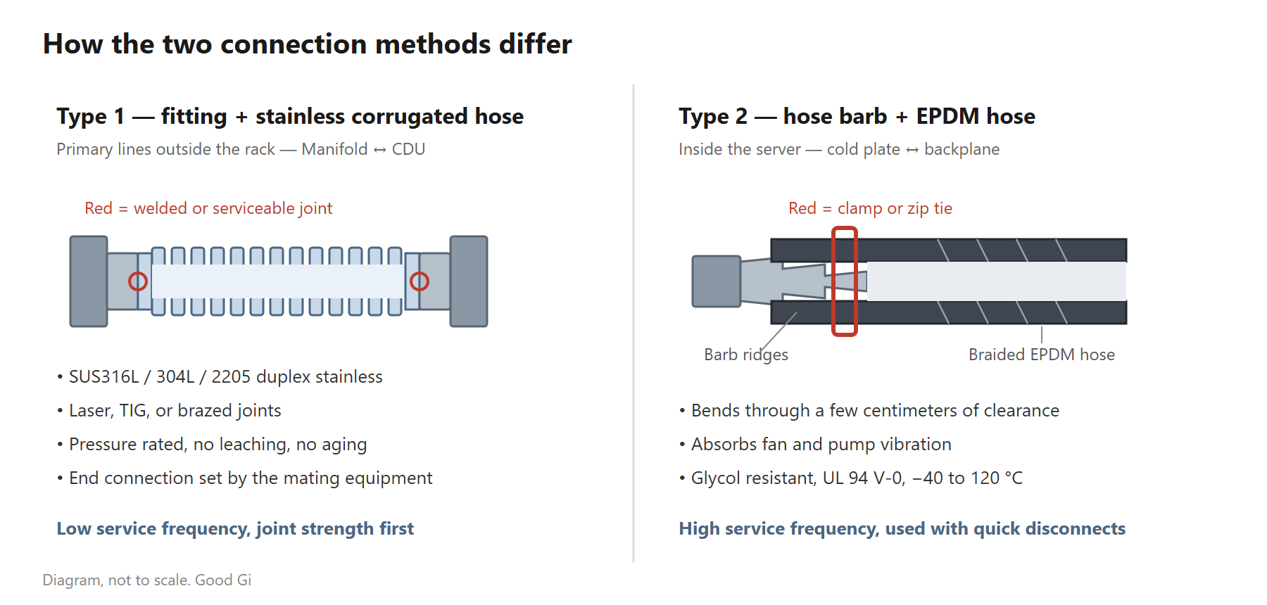
Left: primary level, mostly welded joints. Right: node level, a barbed stem inside the hose held by a clamp. Schematic, not to scale
| Type 1: fitting + stainless corrugated hose | Type 2: barb + EPDM hose | |
|---|---|---|
| Level | Primary lines outside the rack, manifold ↔ CDU | Inside the server, cold plate ↔ backplane |
| Pressure | High: working pressure around 5 bar (about 72 psi), burst pressure in the 150 bar range | Moderate |
| Line size | Large | Small |
| Selection priorities | Pressure, corrosion, no coolant contamination, flame rating | Flexibility, vibration damping, glycol resistance, flame rating |
| Joint type | Mostly welded, serviceable fittings at the maintenance end | Barb and clamp, quick disconnect, blind-mate coupling |
| Service frequency | Low | High |
Neither method is better; they split the work. What has to be decided along the path is where the boundary falls — the point where metal hands off to rubber, usually at the rack manifold or the drawer entry.
Four questions that come up in every design review
Can the primary lines be rubber all the way?
Technically yes, and data centers do build it that way. Braided EPDM hose handles glycol and is available in compounds compliant with UL 94 V-0; it does not need a separate sleeve or a metal conduit around it.
For the primary segment, though, the usual recommendation is still stainless corrugated hose with welded joints. The difference is not whether it can be assembled — it shows up over time:
- Purity: rubber releases trace compounds as temperature and service hours accumulate, and it is not a full barrier to gas permeation either. Coolant circulates in a closed loop for years, and whatever comes out of the wall ends up in the narrow channels of a cold plate. An electropolished 316L wall doesn't shed contaminants, and rubber can't match that.
- Sealing: clamps and barbs rely on clamping force. Rubber takes a compression set, that force decays, and this is the most common starting point for weeping at a primary joint. Welded joints have no clamping force to lose and no gasket to age.
- Replacement cycle: rubber hose has to go into a replacement schedule, and replacing it means downtime or a bypass. Metal hose normally isn't on that schedule at all.
The trade-off is cost, and only cost. At the same primary-line duty, stainless corrugated hose typically runs several times the unit price of EPDM. That is why the common answer in practice is to split the run: braided rubber hose where service is frequent and space is tight, metal and welded joints where nothing is going to move for years.
Can stainless corrugated hose go inside the server?
Rarely. Bend radius and space are the first limit; transmitted vibration is the second. Unless the position is fixed and also needs high-temperature capability, there is little reason to run metal at node level.
Does it matter whether the coolant is deionized water or a glycol mix?
Yes. Compatibility between a glycol-water mix and the rubber and seal materials has to be confirmed separately, and the seal compound (EPDM, FKM, FVMQ, FFKM, NBR, HNBR) is chosen against the coolant formulation. On the metal side, what matters is chloride content and conductivity — deionized water is more aggressive toward some metals than people expect, so set the grade from the actual water analysis.
Can the drain hose and the coolant line be the same part?
No, and it usually costs more to try. A coolant line is pressurized end to end; a drain hose runs on gravity and carries almost no pressure, and its bore is limited by whatever clearance is left under the drip tray. Pressure-rated braided hose used as a drain line is overkill, and it won't be cheaper either. That trade-off is covered in choosing a drip tray drain hose.
What a complete path uses
With both methods covered, here is the whole path in one table, so you can see which segments of your design are still open:
| Path segment | Parts commonly used |
|---|---|
| CDU ↔ manifold primary lines | Stainless corrugated hose, rigid pipe, end fittings |
| Manifold itself | Coolant distribution manifold (CDM) |
| Manifold ↔ node | Quick disconnects (UQD), blind-mate couplings (UQDB) |
| Plumbing inside the node | Hose barbs, braided EPDM hose, clamps |
| Chip ↔ cold plate | Thermal interface materials |
| Drip tray drainage | Flame-retardant SRT silicone tubing |
| Cable protection along the route | Corrugated tubing, heat shrink tubing, fiberglass sleeving |
Each segment is selected on its own criteria: primary lines on pressure and service life, node plumbing on space and serviceability, the drain hose on the clearance left under the tray, and cable protection on temperature and flame rating. No single material covers all of it.