Good Gi supplies tubing and cable protection parts for AI server and HPC racks. This article covers one position in the rack: the drain hose on the drip tray. The part is silicone rubber tubing (SRT).
Sealing specs on liquid-cooled racks keep getting tighter. Nobody designing a data center assumes the seals will hold forever, so the build adds a drip tray at the exposed positions and runs a hose to carry the liquid away. One international power electronics manufacturer, referred to here as Company D, buys that hose from us.
Where the drip trays sit
A rack carries more than one drip tray. Four positions show up in most builds:
| Position | What it catches | Space available |
|---|---|---|
| Rack bottom | The last line of defense for the whole rack, catching whatever runs down from above | Most generous, roughly 30 to 50 mm |
| Connection points (coolant lines and quick disconnects) | Mating and unmating surfaces, where leaks are most likely to start | Depends on how the plumbing and fittings are laid out |
| Top level inside a module | Directly under the cold plate module, closest to both the heat and the live components | Tightest of the four, set by the module structure |
| PCB level or drawer bottom | Whole-layer protection across the board or under the drawer | Shallow, roughly 10 to 20 mm |
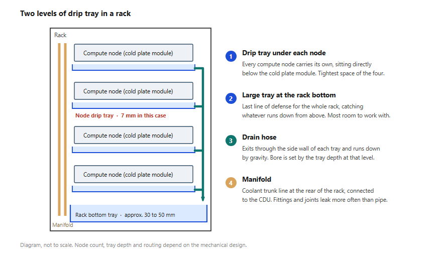
Drip trays work at two levels in a rack: one large tray at the bottom, plus a shallow tray under each compute node. Diagram, not to scale
Position sets the height you have to work with. Height sets how thick the hose can be. So before you pick tubing, find out which level the tray sits on.
How the hose connects to the tray
You drill the tray side wall, pass the hose through the hole, then run it down through the internal cable routing to a designated collection point.
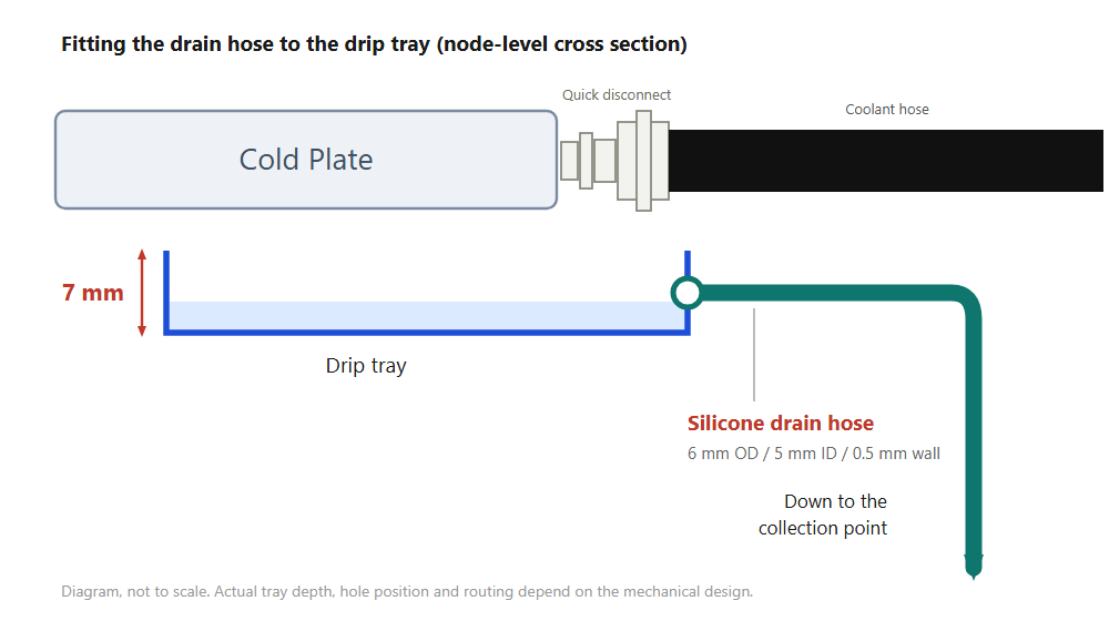
Node-level cross section. Quick disconnects link the cold plate to the coolant hoses; the tray sits below, and the drain hose exits through the side wall. Diagram, not to scale
This hose and the main coolant loop are two different jobs, and the material logic behind them has almost nothing in common:
| Main coolant loop | ▎Drip tray drain hose | |
|---|---|---|
| Job | Feed coolant to the cold plate and carry the heat out | Move escaped liquid away from the equipment |
| Pressure | Pump-driven, under pressure the whole way | Close to zero pressure, gravity does the work |
| Bore | Sized from the flow rate | Sized from whatever tray height is left |
| What matters in the material | Pressure rating, coolant compatibility, temperature range | Thin wall that won't collapse, easy bending, flame retardance, insulation |
Zero pressure does not mean loose specs. The bore on this hose never comes from a flow calculation. It comes from how much tray height you have left.
What Company D needed
| Requirement | How SRT answers it |
|---|---|
| Fits a 7 mm drip tray | 6 mm OD (5 mm ID, 0.5 mm wall), leaving room for the hole and the bend |
| Compliance with UL | Meets the VW-1 vertical flame test in UL 224 |
| Flame retardant | Flame-retardant grade specified; the standard grade in the same family carries no VW-1 |
| Works in tight rack spaces | Silicone springs back, so a 0.5 mm wall holds its shape through a bend instead of kinking |
The tray is 7 mm deep. Across the racks Good Gi has worked on, bottom collection trays usually run 30 to 50 mm, while the shallow protection trays inside a module or under a U sit closer to 10 to 20 mm. At 7 mm, Company D was a step tighter than a normal shallow tray.
The hose exits through the tray wall, so the OD has to leave clearance for the hole and the bend. That put the ceiling at 6 mm. Smaller is not automatically better: a narrower bore carries less water and slows the flow. Gravity is the only thing pushing it. Make the tube too thin, add the bends it takes to get around a wire harness, and the water pools in the tray instead of leaving it. A full tray overflows, and the whole layer of protection stops working.
So the exercise is not to shrink the hose until it fits. It is to find the size that drains fastest inside the height you have. We worked back from drain rate on one side and installation clearance on the other, and landed on 6 mm OD.
SRT silicone tubing specifications

SRT is an extruded silicone rubber tube. White is standard; clear and other colors are made to your sample
| Item | Specification |
|---|---|
| Product | SRT silicone tubing (flame-retardant grade) |
| This application | 5.0 ±0.1 mm ID, 0.50 +0.12/−0.1 mm wall (6 mm OD) |
| ID range | 1 to 20 mm |
| Operating temperature | −50 to +200°C |
| Dielectric breakdown voltage | ≥20 kV |
| Flame retardance | Meets the VW-1 vertical flame test in UL 224 |
| Hardness | Shore A 70 ±5 |
| Color | White as standard; clear and other colors made to sample |
Full range and specifications on the product page: SRT silicone tubing
Thin-wall small-bore tube lives or dies on tolerance. Every size from 1 to 7 mm ID uses the same 0.50 mm standard wall, held to ±0.1 mm on the bore; the wall tolerance on this application's 5.0 mm size is +0.12/−0.1 mm. Let the tooling or the cooling drift and the wall comes out thick on one side and thin on the other, and the thin side collapses first when you bend it. Hold that tolerance and the size becomes usable.
Clear compound earns its place here. The hose runs inside the rack, so a technician can see whether liquid is sitting in it without pulling anything apart.
One boundary worth stating: Good Gi does not make leak detection sensors. This hose handles where the liquid goes after it escapes. Detection is somebody else's part.
Where else this applies
If all you need is a tube to move water, cheaper options exist. This one goes inside electrical and mechanical equipment, so it clears the same safety review as everything else in the enclosure: flame retardance, UL, insulation, temperature. Price only becomes the question once the specification matches.
SRT covers several of those at once:
- Flame retardance: the flame-retardant grade meets the VW-1 vertical flame test in UL 224, suitable for routing alongside a wire harness
- Insulation: ≥20 kV breakdown voltage and 2×10¹² Ω·cm volume resistivity, suitable for routing close to live terminals
- Temperature: −50 to +200°C covers rack temperature rise and ambient swing
- Toughness: 6.9 MPa tensile strength, 200% elongation at break, 14.5 kN/m tear strength, so pulling and repeated flexing do not split it
- Installation: Shore A 70 ±5 plus silicone spring-back keeps a thin wall in shape through a bend in a tight space
- Maintenance: clear compound to your sample, so technicians can see residual liquid on site
- Sizes: 1 to 20 mm ID are all standard, with no tooling charge for a single size
Bottom tray, connection point or inside a module, the reasoning stays the same. Measure the tray height you have, work back to the OD ceiling, then check that the bore still drains along the bend path you actually need. Space is the only variable. At 7 mm your options get narrow; at 30 mm and up you have room to choose.