Data center power architecture is in the middle of a generational change. Most of the discussion so far has been about topology, conversion efficiency, breakers, and connectors. The insulation on the busbars has had far less attention. This article covers the 800 VDC deployment timeline, what the February 2026 revision to UL 224 changed, and where that leaves an engineer who has to specify insulation this year.
1. The 800 VDC timeline already has dates on it
In October 2025, NVIDIA published its 800 VDC ecosystem partner list, split across three layers: semiconductors and chips, power system components, and data center power systems. The component layer names Delta, BizLink, Flex, and LITEON, among others. The data center power system layer names ABB, Eaton, Schneider Electric, Siemens, Vertiv, and Hitachi Energy, among others.
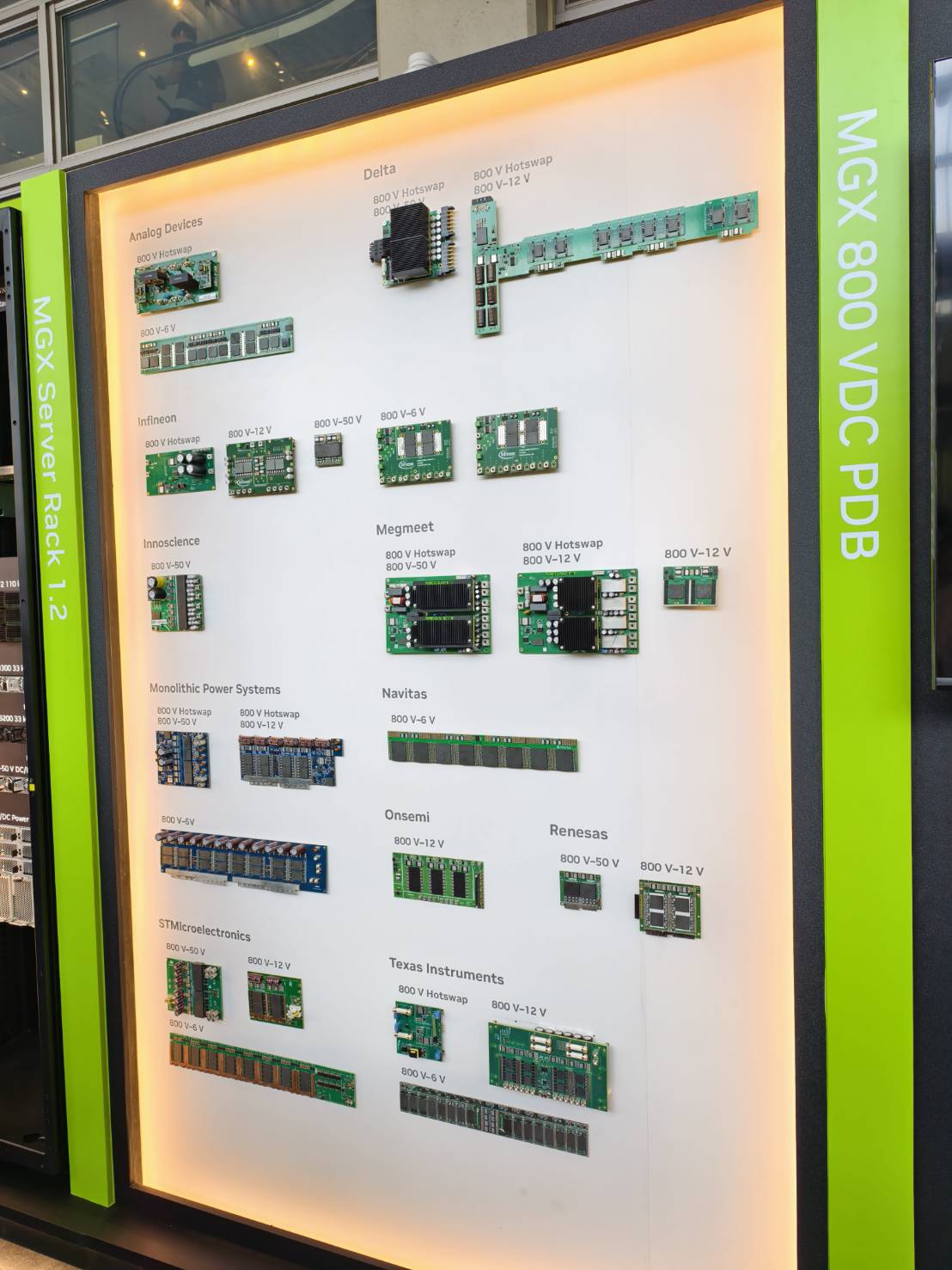
NVIDIA's MGX 800 VDC power distribution board at COMPUTEX 2026. The power modules are already broken out by function: 800V Hotswap, 800V to 50V, 800V to 12V. At component level, 800 VDC has moved into hardware. (Photographed at the show.)
Rack power drove the change. A single AI chip is about to pass 2 kW. Vertiv puts the crossover at 300 kW per rack, the point above which 800 VDC starts to pay for itself. At that level, a conventional 54 V architecture needs more copper than the rack can carry and loses too much in conversion. Delta's published figures show that the traditional path from 10 kV down to 0.65 V at the GPU takes six conversion stages; a solid-state transformer (SST) architecture cuts that to two, with medium-voltage AC to 800 VDC running at 98.5% efficiency.
Where the major power vendors stand:
| Date | Vendor | Progress |
|---|---|---|
| Oct 2025 | Eaton | 800VDC reference architecture prototype shown at OCP Global Summit |
| Oct 2025 | ABB | Partnership with NVIDIA on next-generation AI data centers, targeting 2027 deployment |
| H2 2026 | Vertiv | 800VDC product line launch, matched to NVIDIA Kyber and Rubin Ultra |
| 2026 | Siemens | SENTRON 3VD 800/1000V DC molded case circuit breakers |
Moving from AC to DC changes what the insulation has to survive
DC insulation requirements are not the same as AC ones. An AC waveform crosses zero twice per cycle, which gives partial discharge a chance to self-extinguish. DC has no zero crossing, so once an arc strikes there is nothing to put it out. Power density adds to the problem, because the same volume now stores far more energy than before. So does the humidity that comes with liquid cooling, which accelerates electrochemical migration under DC.
The insulation layer has to hold off the voltage and survive those conditions for the service life of the installation.
NVIDIA's own ecosystem document says the industry needs to agree on a common voltage range, on connector interfaces, and on safety practices for 800 VDC environments. The large vendors are moving the first two forward. On the third, once you get down to the material layer, the document does not mention insulation class, creepage distance, or dielectric withstand certification. Trade press covering the same announcement flagged the same gap.
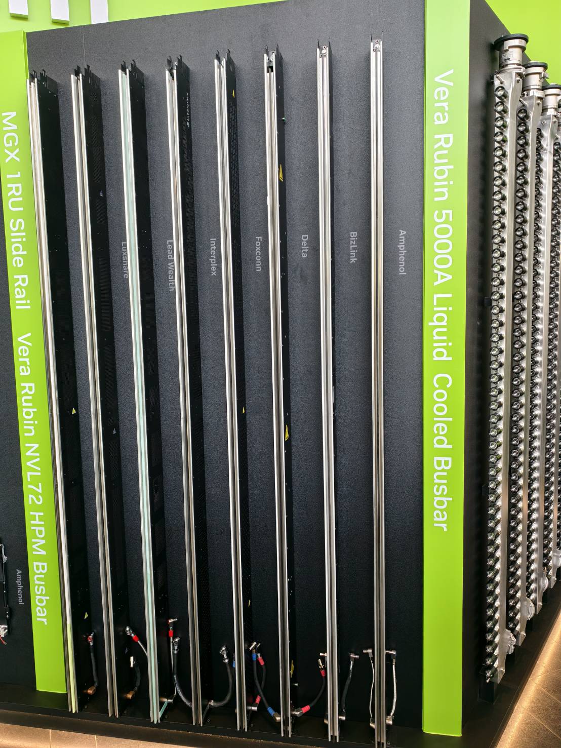
The Vera Rubin NVL72 busbar and the 5,000 A liquid-cooled busbar, shown in the same hall. These are the busbars this article is about. (Photographed at the show.)
2. Sleeving is certified to UL 224, and UL 224 tests with AC
In North America, insulating sleeving used in data center builds is certified under UL 224, which covers extruded insulating tubing and includes heat shrink sleeving. The standard sets three voltage ratings: 150 V, 300 V, and 600 V. Not every material can claim all three.
| Material | Voltage ratings available |
|---|---|
| PVC | 300V / 600V (no 150V) |
| Polyolefin (heat shrinkable) | 150V / 300V / 600V |
| PTFE, FEP | 150V / 300V / 600V |
| PVF2, modified fluoropolymer, chlorinated polyolefin | 600V only |
| Silicone rubber (wall thickness under 0.711 mm) | 300V only |
Source: UL 224, Standard for Safety for Extruded Insulating Tubing, 6th edition, Table 1.
That ceiling sat at 600 V for years. It moved in February.
What UL 224 Edition 8 changed
ANSI/UL 224 Edition 8 was published on 13 February 2026. It adds two optional ratings: sunlight resistance, and a higher voltage rating that takes the ceiling to 2,000 V. UL lists the applications it is aimed at: battery energy storage, EV charging, photovoltaics, and DC microgrids. The higher voltage rating is available for new certifications and can be added to existing ones.
How the dielectric withstand test is run
The method is simple. A conductor is placed inside the tubing, metal foil wraps the center section on the outside, and a 60 Hz sinusoidal AC voltage is applied between the two and held for one minute. The voltage is then raised until the sample breaks down.
The procedure uses AC. The standard does not specify a DC dielectric withstand procedure.
That difference matters for DC applications. Apply DC to an insulator and the current through it has three components: charging current, absorption current, and conduction current. Once the first two decay, what remains is a steady leakage current, and that steady value is the direct indicator of insulation quality. An AC test measures capacitive current instead. The two tests do not measure the same property.
Design rules already cover DC. Product testing still runs on AC
Insulation coordination standards covered DC long ago. IEC 60664-1 covers both AC and DC up to 1,500 V DC, and at 800 V DC, pollution degree 2, material group IIIa, it gives a minimum creepage distance of 8 mm. IEC 61439-1, Table 2, gives 12.5 mm for the equivalent case.
The two figures differ because they apply at different levels:
| Minimum creepage | Applies to | Standard |
|---|---|---|
| 8 mm | Electronic circuits and board-level equipment; the tighter design value | IEC 60664-1 (component level) |
| 12.5 mm | Switchboards and assemblies; the value used in build practice | IEC 61439-1 (system level) |
So the design side has rules to work from, and DC was written into them from the start. Product testing is a separate matter: sleeving is certified to UL 224, and the UL 224 dielectric withstand method uses AC. As far as we have been able to establish, UL does not yet publish a product voltage rating specific to 800 V DC.
So we ran our own round of DC testing. Customers are designing 800 VDC systems now, and the reference data available to them stops at AC. Rather than wait for the standard to catch up, we tested under both AC and DC, and recorded the conditions alongside the results.
3. Good Gi parts by position, with in-house dielectric withstand data
The tables below map what we can supply to each position on the data center power path, alongside our own dielectric withstand results. Every figure was measured in our own laboratory in Taiwan. None of them are third-party certified ratings, and the test conditions are available on request.
3-1 Parts by position on the power path
Part names link through to the product pages.
Busbar insulation, from the medium-voltage incomer through to rack distribution
| Position on the power path | Part | Material | Temperature range |
|---|---|---|---|
| MV incomer to SST primary | 10KV Busbar Heat Shrink Tubing | Polyolefin (PE) | -40 °C to 125 °C |
| MV incomer to SST primary | 20KV Busbar Heat Shrink Tubing | Polyolefin (PE) | -40 °C to 125 °C |
| MV incomer to SST primary | 35KV Busbar Heat Shrink Tubing | Polyolefin (PE) | -40 °C to 125 °C |
| SST secondary to 800VDC busbar | 1KV Busbar Heat Shrink Tubing | Polyolefin (PE) | -40 °C to 125 °C |
| Power rack to rack distribution | 1KV Busbar Heat Shrink Tubing | Polyolefin (PE) | -40 °C to 125 °C |
The 1KV, 10KV, 20KV, and 35KV in the part numbers are series designations. They indicate the switchgear voltage class each series is intended for, not a third-party certified voltage rating for the product.
Harness and joint insulation inside the rack
| Part | Material | Temperature range | Shrink ratio |
|---|---|---|---|
| GHT halogen-free PE heat shrink tubing | Polyolefin | -55 °C to 125 °C | 2:1 |
| GDW halogen-free adhesive-lined heat shrink tubing | PE with hot melt adhesive | -55 °C to 125 °C | 3:1 |
| GP-600V-CR cold-resistant extruded PVC tubing | PVC | -40 °C to 105 °C | — |
GP-600V-CR tops out at 105 °C, the lowest in this table. In a liquid-cooled rack held below 40 °C there is still margin, but use one of the fiberglass parts for the hot sections.
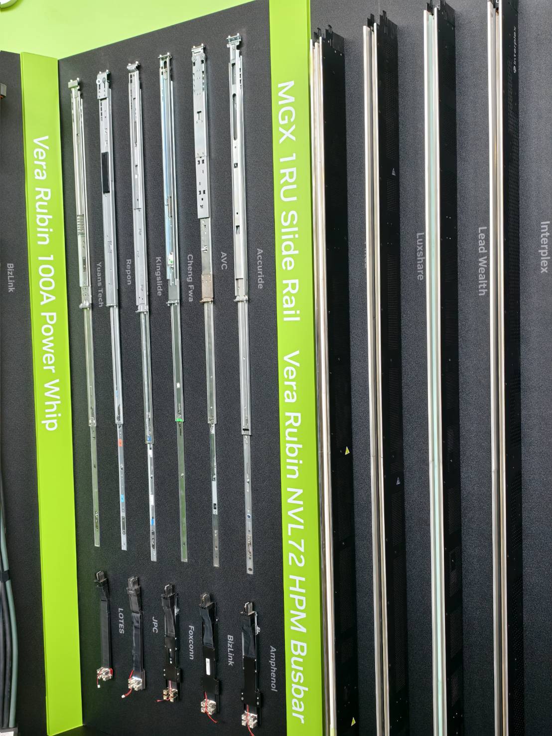
The Vera Rubin 100A Power Whip on display. Harnesses and joints inside the rack are the other place insulating sleeving is used. (Photographed at the show.)
High temperature and special temperature ranges
| Part | Material | Temperature range |
|---|---|---|
| FSHTG Class H flame-retardant high-temperature fiberglass sleeving | Glass yarn, silicone resin | -40 °C to 260 °C |
| GF-40 fiberglass silicone sleeving | Glass fiber, silicone resin | -10 °C to 200 °C |
| GSRT-70 fiberglass silicone sleeving | Glass fiber, silicone resin | -10 °C to 200 °C |
| GDPTFE PTFE heat shrink tubing | PTFE | -65 °C to 220 °C |
| GKY KYNAR PVDF 175 heat shrink tubing | PVDF | -55 °C to 175 °C |
| HFEP FEP 200°C heat shrink tubing | FEP | -65 °C to 200 °C |
| HSRT silicone rubber heat shrink tubing | Silicone rubber | -60 °C to 200 °C |
3-2 In-house dielectric withstand results, by voltage level
| Part | Temperature range | AC 600 V | AC 1000 V | DC 800 V | AC 1500 V | AC 2000 V | AC 2500 V |
|---|---|---|---|---|---|---|---|
| 1KV Busbar Heat Shrink Tubing | -40 °C to 125 °C | ✓ | ✓ | ✓ | ✓ | X | X |
| 10KV Busbar Heat Shrink Tubing | -40 °C to 125 °C | ✓ | ✓ | ✓ | ✓ | ✓ | ✓ |
| 20KV Busbar Heat Shrink Tubing | -40 °C to 125 °C | ✓ | ✓ | ✓ | ✓ | ✓ | ✓ |
| 35KV Busbar Heat Shrink Tubing | -40 °C to 125 °C | ✓ | ✓ | ✓ | ✓ | ✓ | ✓ |
| GHT halogen-free PE heat shrink tubing | -55 °C to 125 °C | ✓ | X | X | X | X | X |
| GDW halogen-free adhesive-lined heat shrink tubing | -55 °C to 125 °C | ✓ | ✓ | ✓ | X | X | X |
| GP-600V-CR cold-resistant extruded PVC tubing | -40 °C to 105 °C | ✓ | X | X | X | X | X |
| GSRT-70 fiberglass silicone sleeving | -10 °C to 200 °C | ✓ | ✓ | ✓ | ✓ | ✓ | ✓ |
| GDPTFE PTFE heat shrink tubing | -65 °C to 220 °C | ✓ | ✓ | ✓ | ✓ | ✓ | ✓ |
| GKY KYNAR PVDF 175 heat shrink tubing | -55 °C to 175 °C | ✓ | ✓ | ✓ | ✓ | ✓ | ✓ |
| HFEP FEP 200°C heat shrink tubing | -65 °C to 200 °C | ✓ | ✓ | ✓ | ✓ | X | X |
| HSRT silicone rubber heat shrink tubing | -60 °C to 200 °C | ✓ | ✓ | ✓ | ✓ | ✓ | X |
This table records Good Gi laboratory measurements, not third-party certification. Applied voltage, electrode configuration, and pass criteria for each level are available on request. The table stops at AC 2500 V because that was the range set for this round of testing, not because the materials stop there.
GSRT-70 is a braided fiberglass sleeve with a silicone coating, a construction that falls outside the scope of UL 224. Its results here come from the same in-house round as the rest of the table, and they are not UL 224 ratings.
Use these figures as a starting point and check them against your own operating conditions. For the full test specification, or to request samples, talk to our engineers.
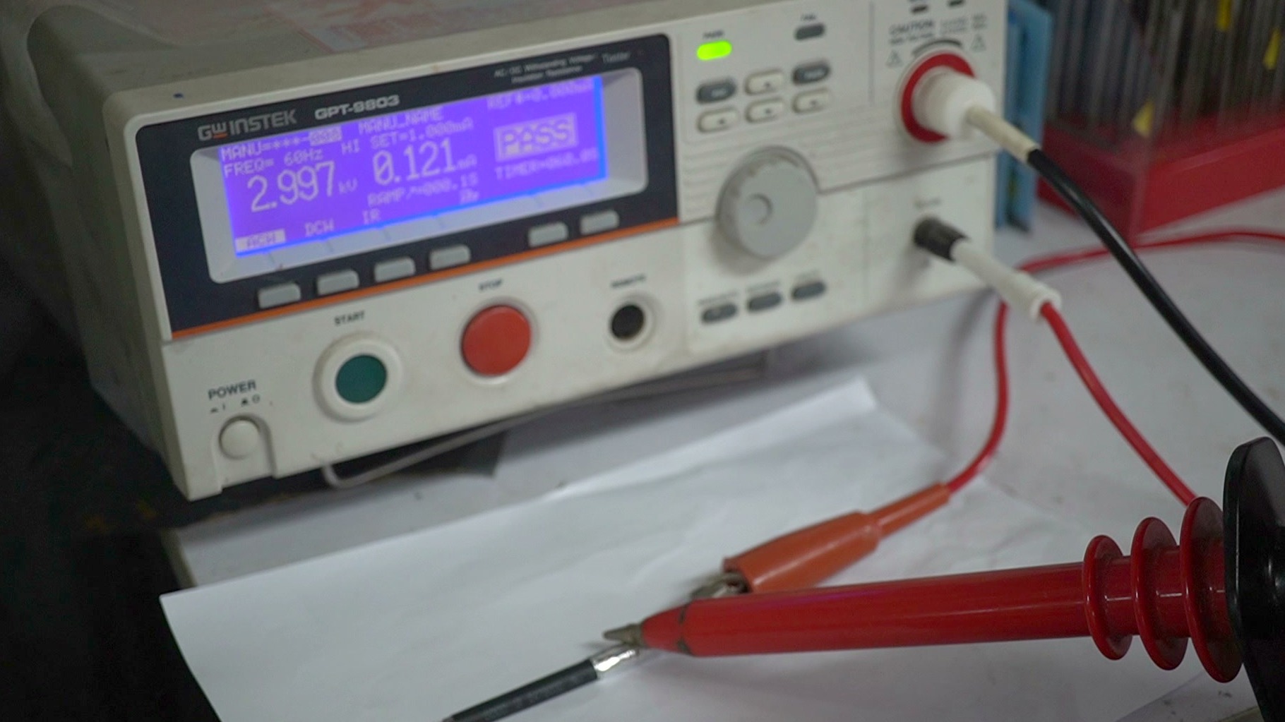
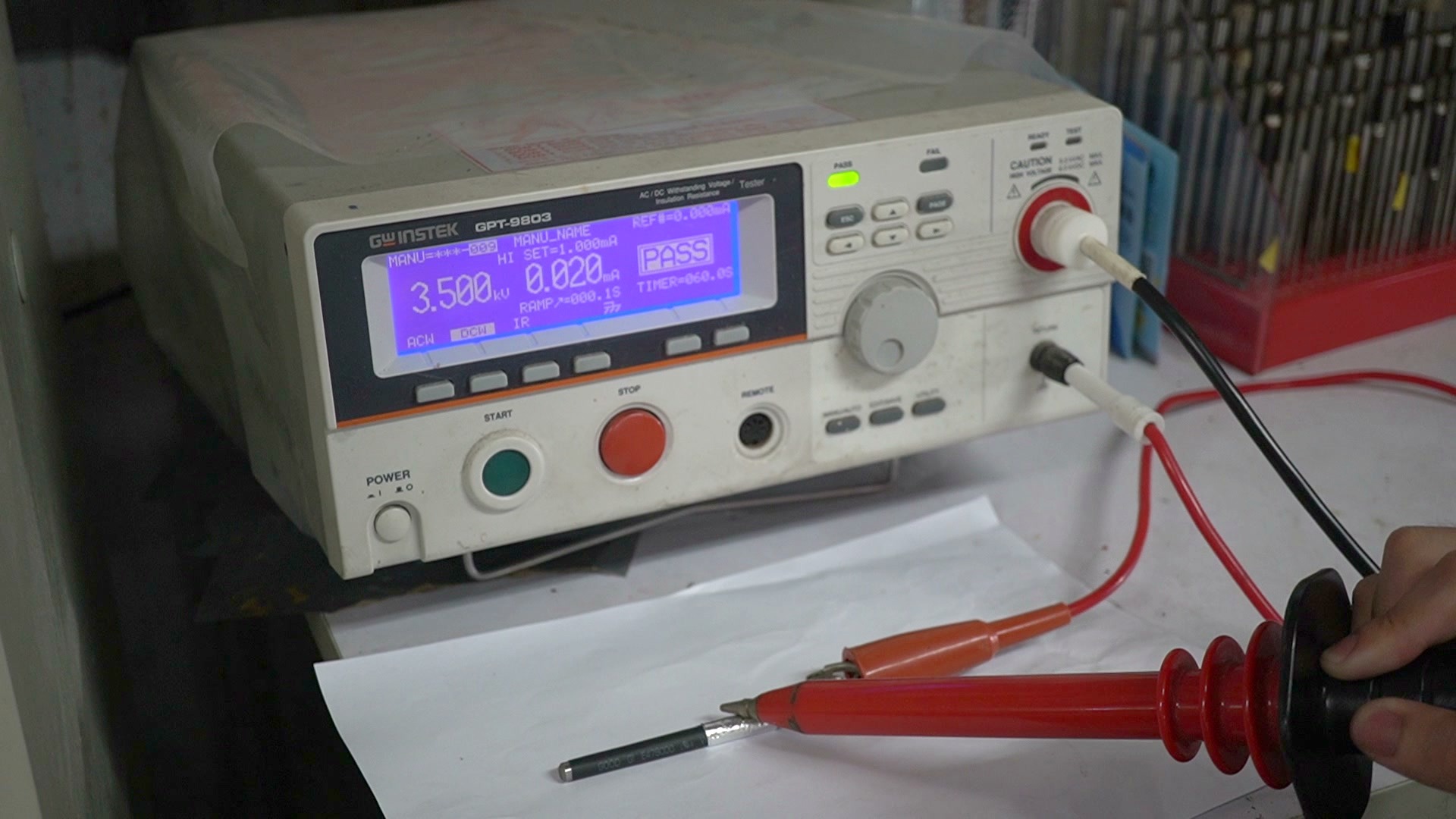
Test equipment: GW INSTEK GPT-9803 AC/DC dielectric withstand and insulation resistance tester (Good Gi in-house testing).
4. What you can specify while the standards catch up
Conversion efficiency, breakers, and connector specifications for 800 VDC all have large vendors behind them. How medium voltage gets down to 800 V DC is still contested: Schneider Electric puts forward both solid-state transformers and conventional rectification, while Delta backs the SST architecture. Either route ends with busbars and harnesses that have to be insulated, and that requirement does not change with the topology.
There is no off-the-shelf answer for that layer yet. The design standards give you creepage distances; product certification stops at AC. Until that changes, we test under both conditions, record what we did, and give your engineering team figures it can check.
Good Gi has been a long-term supplier to power supply manufacturers named on that ecosystem list.
If you are working through insulation selection for an 800 VDC architecture, get in touch:
- Request the full in-house dielectric withstand test report, including test conditions and measurement method
- Selection help: which part goes where on the power path
- Samples and lead times for any part in the tables above
- Third-party certification: timing, and how we can fit it to your project schedule
Use the contact form, the email link on this page, or any inquiry button on the site. One of our engineers will answer.
Sources used in this article
| Cited content | Source |
|---|---|
| UL 224 voltage rating classes (Table 1) | UL 224 Standard for Safety for Extruded Insulating Tubing, 6th Edition (6 March 2006), Table 1 |
| UL 224 Edition 8 adds higher voltage and sunlight resistance ratings | UL Solutions: Insulating Tubing Testing and Certification |
| UL 224 Edition 8 publication date and edition | UL Standards & Engagement: ANSI/UL 224 Edition 8 (13 February 2026) |
| 800VDC ecosystem three-layer partner list; insulation requirements not covered | NVIDIA Developer Blog: Building the 800 VDC Ecosystem for Efficient, Scalable AI Factories (13 October 2025) |
| SST conversion efficiency 98.5%, six stages cut to two | Delta Electronics press release: Delta's Power, Cooling and Microgrid Solutions Showcased at NVIDIA GTC |
| ABB targeting 2027 deployment | ABB press release: ABB to Develop Next-Generation AI Data Centers with NVIDIA |
| Eaton 800VDC reference architecture prototype | Eaton press release: Eaton Unveils Next-Generation Architecture |
| Vertiv 800VDC product line, H2 2026 | Vertiv press release: From Vision to Readiness, Vertiv Collaborates with NVIDIA on 800 VDC Platform |
| Siemens 800/1000V DC molded case circuit breakers | Siemens press release: Siemens Launches Groundbreaking Portfolio for the Era of Direct Current Technology |
| Two technical routes for MV to 800VDC conversion | Schneider Electric Insights: 800 VDC, Powering the Future of AI Data Centers |
| Industry discussion lacking insulation class and dielectric certification detail | Data Center Frontier: Preparing for 800 VDC Data Centers, ABB, Eaton Support NVIDIA's AI Infrastructure Evolution |
| Charging, absorption and conduction current under DC | Kikusui America: DC Withstand Voltage Testing |
| Dielectric withstand pass criteria and steady-state leakage current | Vitrek: Dielectric Withstand Test, A Complete Guide to Insulation Safety and Compliance |
| Minimum creepage 8 mm / 12.5 mm at 800 V DC | IEC 60664-1 insulation coordination for low-voltage systems, IEC 61439-1 low-voltage switchgear assemblies (full text is paid access) |