Thermal Management Optimization Case Study for COF Areas in TV Panels
Application Background
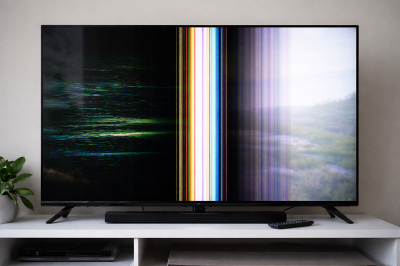
In large-size LCD TV applications, COF Driver ICs (Chip-on-Film) mounted on the Source Board become major heat sources during long-term operation. As requirements for 4K resolution, high-brightness backlight, and advanced image processing continue to increase, both power consumption and heat density of COF ICs have risen accordingly.
- IC junction temperature (Tj) partially exceeds the specified upper limit
- Heat accumulates in localized regions with insufficient in-plane heat spreading
- Temperature reaches a steady-state high-temperature condition after prolonged operation
- Long-term reliability margin, image stability, and IC lifetime are negatively impacted
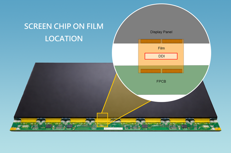
In this structure, COF ICs do not incorporate active cooling mechanisms. The primary heat dissipation path is:
IC → FPC / adhesive tape → metal back plate → natural convection
As a result, interfacial thermal conduction and in-plane heat spreading capability become the dominant factors determining IC junction temperature (Tj) under steady-state conditions.
Customer Test Results and Feedback
Test Conditions
- Test model: 43” LCD TV
- Test duration: 2 hours continuous operation (steady-state)
- Measurement method: Thermocouples attached to COF ICs and bonding areas
- Evaluation criterion: Customer-defined COF IC Tj specification
Comparison Test Setup
- Without thermal tape: No carbon-copper thermal tape applied
- With carbon-copper thermal tape: Applied to COF area
Key Measured Results (Ambient: 45°C)
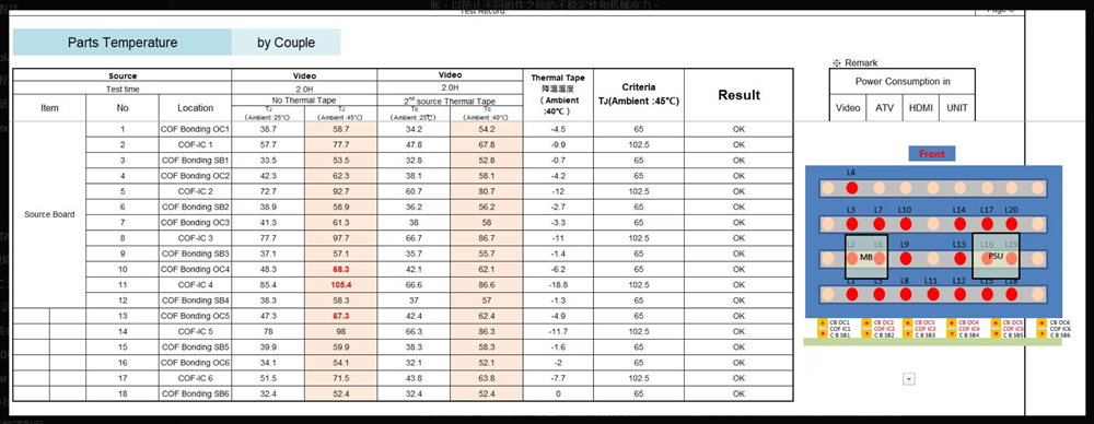
- Customer-defined COF IC Tj upper limit: 102.5°C
- Without thermal tape, COF-IC4 exceeded specification at 105.4°C
- After applying carbon-copper thermal tape, all measurement points returned within specification (Result = OK)
Engineering Observations
- Temperature reduction correlates positively with IC power consumption
High heat-density ICs (IC4, IC2, IC5) showed the most significant improvement, with a maximum reduction of 18.8°C. - System-level thermal behavior improvement
Temperature reduction was observed across all COF IC measurement points, not just a single localized hot spot. - Validated under steady-state conditions
Results represent long-term thermal equilibrium rather than short-term peak temperature.
Engineering Benefits and Selection Rationale
Reliability and Lifetime Improvement
IC lifetime exhibits an exponential relationship with operating temperature, as described by the Arrhenius model. Reducing COF IC temperature by 10–20°C provides a substantial improvement in MTBF (Mean Time Between Failures).
Addressing Insufficient Heat Spreading
Conventional thermal interface materials mainly compensate for mechanical tolerances and reduce contact thermal resistance (Z-axis conduction). However, the core issue in this case is localized heat accumulation caused by insufficient in-plane heat spreading.
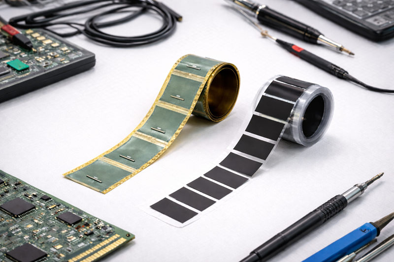
Material Characteristics of Carbon-Copper Thermal Tape
- Graphite layer with high in-plane thermal conductivity for rapid heat spreading
- Copper foil layer with high thermal capacity for stabilizing heat distribution
- Ultra-thin tape structure suitable for mass-production assembly
Passing Specification, Not Just Lower Temperature
- Out-of-spec measurement points brought back into compliance
- Improved thermal design margin
- Reduced long-term high-temperature failure risk
In fanless and thickness-constrained products, carbon-copper thermal tape is one of the most effective passive heat spreading solutions available.
Conclusion
- IC junction temperature reduced by up to 18.8°C
- Out-of-spec points returned within specification
- Improved long-term operational stability
- Enhanced overall thermal distribution and reliability
This material represents a highly efficient and mass-producible thermal management solution for large-size TVs, display modules, and electronic products without active cooling.